Showing posts with label sammichfm. Show all posts

10 December 2011

Building SammichFM DIY Video

This year I build a Wilba SammichFM DIY synthesizer kit. It is based on the famous Yamaha OPL3 sound chip that was also used on the famous Sound Blaster Pro 2.0 and SoundBlaster 16 ASP sound cards. It is a 4 voice FM synthesizer that sounds a lot like the famous Yamaha DX series. During the construction of the synthesizer I filmed the whole process. This movie is an excerpt of the 4 hours total build time. I made the 3D animations myself in Cinema 4D. The music you hear in the background in a track called 'Thermosphere' from my 'AtmoSphere' album that I released in 2008. More information on the album on http://www.synth.nl/AtmoSphere.

17 November 2011

SammichFM (Part 7)

The next step in the process of building the SammichFM is the painting of the letters for the front and back panels. The idea is that you put paint on the paper that is on the panels and then peel it of to reveal the letters. Somehow that is not really my thing :) I always end up having paint everywhere. Maybe I'm to impatient I don't know. But somehow I also do manage to get it of with some thinner and don't screw up that bad, so it kind of looks OK I think.

The most tricky part is that the inside of letters like 'P' stay on when you peel of the paper and you have to get that of somehow and if the paint is not completely dry yet, you smear it out. Ah well now you are warned at least ;). On the right is a picture of the back panel. As you can see it has two audio outputs. You can assign any of the four parts of the synthesizer to an output, so it is a real multitimbral synthesizer actually. Quite  more than I expected when I started to build it.

And here is a picture of the fully assembled and fully operational end product. The SammichFM :) On top you can clearly see the buttons to select the 4 parts of the synthesizer. So you really get 4 for the prince of 1. Looking back on this project I think it is not a beginners project. Especially the soldering of the SMD components is quite challenging and not suitable for anyone without proper soldering experience. The rest is fairly simple, so maybe get some help if you want to build one for yourself and you are not so experienced.

And here is one final picture: a nice family portrait. On the left is the SammichFM and on the right its sister the SammichSID. Nice shot I think :) I personally like the blue leds and blue backlit display better on the SammichFM. But to conclude this series: These synthesizers are very similar in looks, but very different in character. The SammichSID is way more analog sounding and fat, but the SammichFM is very complementary I think.and they make a nice set together. OK now I'm going to work on the movie and hopefully I'll be able to show that any time soon.

15 November 2011

SammichFM (Part 6)

In the last post I was at the point that the MIOS booted OK and now it was time to take it to the next level and program the software for the SammichFM. To do this you hook it up with the Midi input and output to your PC and run an application called MIOS studio. It actually talks to the processor of midi. It didn't work to begin with and after a few minutes I found out that one jumper on the main PCB was in the wrong position. After changing this the software was uploading alright.

The uploading of the software doesn't even take that long, but after that the SammichFM reboots and at first boot it starts to format it's memory banks. Since there are quite some installed by default that process takes a little while. Then finally after that you have a working synthesizer. So the big question was if it would actually produce sounds as well. I still was not sure about the soldering of those SMD components.

So I hooked up a midi keyboard and it worked! :) Always a very satisfying feeling when you can actually play on a synthesizer that you just build with your own hands. There was just one odd thing, there was only one preset in there. After reading a bit in the documentation I found out quickly that this was normal behavior and that you had to put in the factory presets by uploading a sysex file to it over midi. So I did and had some fun with it. It is a nice polyphonic synthesizer and it sounds very .... FM like :) Reminded me right away of the Yamaha DX series that were very popular in the 80's. All in all a very musically usable machine I think :) OK. Enough for today. Next up is to finish up the enclosure. Coming soon!

14 November 2011

SammichFM (Part 5)

With the electronics all done it is time to assemble the case. It is made up of several pieces of plastic that are hold together by bolts and nuts. It is kind of a sandwich construction with a bottom panel and top panel and the side panels will be squeezed between those eventually. In the picture on the left you can see the bottom panel of the whole construction. I only think I will add some rubber things under the case since now the screws are sticking out.


Then on top of this the base PCB is mounted. And on top of that go the spacers that will support the front panel PCB. On the left of the base PCB you can see the connectors that will eventually connect the base PCB and the front panel PCB. It provides power to the front panel PCB, but also the IO of the display, knobs, leds and rotary encoder. So it is kind of a bus system. Very clever I think. No need for extra wiring at all.

And on the left is a picture of the whole sandwich. Again some spacer go on top of the PCB that will eventually support the front panel it itself. I think this is quite an ingenious construction actually that Wilba came up with. It allows for easy access of the PCB's and it keeps everything easy and tidy. I'm not too good with mechanical stuff and case building, but even I can do this :) The rest of the case construction will follow later.


So when that done it was time to put the power on it and see if it actually was doing anything :) After switching it on you can see in the picture on the right that it worked. It shows 'Ready' in the display. Telling that the MIOS operating system is running on the PIC. It is kind of like the BIOS of a PC, but not the Operating System yet. Through this MIOS system you can upload software in the Midibox based synthesizer and that software determines its functionality. So that will be the next step in the next post. So far so good :) Still no smoke ;)

13 November 2011

SammichFM (Part 4)

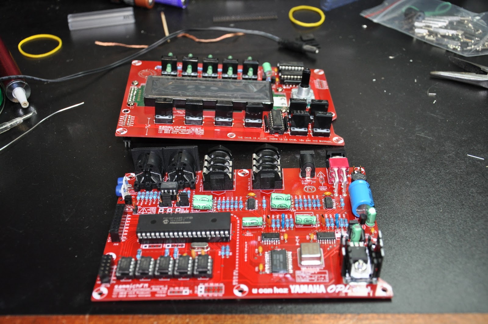
The next step in the building of the SammichFM is to solder all the components on the front panel PCB's. In this picture you can see all the IC sockets, switches, transistors, resistors and capacitors already on the PCB. Actually this is a quite straight forward job. Only on the bottom two right switches you have to cut the leads very short, because otherwise they would touch the heat sink of the power regulator on the base PCB when the whole synth is assembled. Something not to forget.

Then you have to put some spacers on the PCB again. This time to put the front panel in place in order to solder the leds in place. By putting the front panel on, you can stick the leds through the holes simply by turning everything upside-down. Then the leds fall into their intended positions. Because the whole thing is upside-down the leds can't fall out anymore and you can solder them on the bottomside. A simple trick but very effective. Everything looks good.

After this the PCB's are done and it is time to do some power tests, just to see if there are no short circuit. Everything turned out OK, so I put in all the IC's. Basically the electronics part of the project is done now, so it was time for the famous 'smoke test'. I put power on the construction while holding the upper PCB up so that nothing touched each other. And they after applying power feel the IC's to check if they get hot. Well no temperature and no smoke. So all looks great.

And here is a final picture with both finished PCB's. So far I still filmed the whole process and I'm into 3 hours of film by now. Which means I build the whole thing effectively in three hours, but of course over a period of a couple of days. Usually I spend about an hour a day working on a project like this. The next thing will be to assemble the whole case and test the synthesizer. I'm very curious if it will work of course. I'll let you know soon!

10 November 2011

SammichFM (Part 2)

The next task in building the SammichFM was to install all the resistors. As you can see they are all 1% resistors and I always find it challenging to read the color codes on those. You easily mistake a 1K for a 10K resistor, so I tend to measure them all with a multimeter. Just to be sure. Luckily the resistor values are written on the PCB of the SammichFM, so it is easy. So measure a resistor and look for it on the PCB. You don't even need a part list for this process.

After the resistors it was time for the IC sockets Nothing difficult about that. The only trick I always use is to hold them with one hand with the PCB up-side-down and solder just one pin on the edge with the other hand. Then I look if it is in straight and if not I reheat just that one pin and readjust it. When you have already soldered multiple pins that is almost impossible. Then I solder the diagonal opposite pin (furthest away) and check again. After this you can solder the rest, since the socket can't move anymore.

Then it was time for the capacitors. And also a ferrite bead, a crystal and two diodes. Especially for the latest two you need to pay attention because their orientation matters. So far all the components are very flat and in this way you can easily roll the PCB over and solder on the bottom side. This, of course, is also the reason why you should solder in your components in this order. If you start with the highest components you lose this advantage.

And here a final picture of the OPL3 chip more up close, just because I thought it was a nice picture :) You can also clearly read the text on it. The PCB is full with little 'Easter Egg' jokes by the way. Wilba must have been in a very funny mood when he designed it, but I enjoy them while working. Not everything in life has to be so serious. I'm also still filming it all and it looks like I'll have enough nice material later on. In the mean time I've put my camera on permanent power, so that an empty battery won't spoil the fun again. Next post coming soon!

09 November 2011

SammichFM (Part 1)

Today I started a new DIY project as well. I'm going to build a SammichFM synthesizer. Like the name suggests it is a sister of the SammichSID, but this time not based on the Commodore SID chip  but on the Yamaha OPL3 chip (also know as YMF262). This was also a famous sound chip from the 8 bit computer era. It is a 4 voice stereo FM synthesizer. It was used on several famous sound cards like the Sound Blaster Pro 2.0 and the Sound Blaster 16 ASP.

The first task in building this kit is right away the most challenging one as well. The sound chip and 4 other components are so called SMD components. SMD components are surface mounted which means they don't have leads sticking through holes in the PCB, but they rest flat on the PCB and you have to solder the pins to pads on the PCB surface. These pads are very small and very close together. I did need my glasses for this and a magnifying glass to check if I did everything right afterwards.

Wilba was so nice to put some flux in the kit to help improving the flow of the solder. That made things a bit easier. I did solder some pins together though. (It is almost undo-able not to make this mistake by the way) So you need some means to remove excessive solder as well. I used my de-solder pump for this. But in the end I got it right. In the picture on the left you see the remaining parts that I still have to put on there. But those are all conventional 'trough hole' components, so that should be a lot easier :)

Next to taking picture for my blog, I'm also filming most part of the construction of the SammichFM. So hopefully I can show you a nice video as well when it is done. Only during my work I'm not paying much attention to the camera of course and today already the battery ran out during filming and I didn't see that until after I had put on all the SMD components. I just watched how far it filmed and I have enough I think to show the process, even though I can't film to close but I guess you'll get the idea. OK enough for today. I'll continue this project soon and I will post updates on this blog from time to time.