30 November 2011

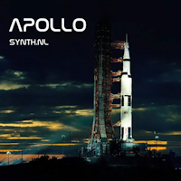
Apollo on CDBaby.com as CD and MP3 Download

I have good news for all of you living overseas (well from my point of view). My Apollo album is now also available on CDBaby.com. If you order the CD there from outside Europe it will save you serious on the shipping costs. I think this is just in time for your Christmas Shopping ;) You can also download it as an MP3 download in high quality if you don't want to wait.

You can find it on this URL: http://www.cdbaby.com/cd/Synthnl3

My other CD's are also for sale on CDBaby.com of course you can find them on this URL: http://www.cdbaby.com/Artist/Synthnl. Thanks for your support!

27 November 2011

BIT Project (Part 1)

At the moment I'm working on quite a big and ambitious project. If you have read my biography you will know that music is just a hobby for me and that my main job is actually operating a business ISP company that is running a couple of data centers in The Netherlands. Our current website is Dutch only and needs a big overhaul. I'm currently working with my colleagues on some ideas for the new website. The first this is that is needs to go in a multilingual CMS system. So the good news is that you guys will be actually able to read it later on :)

One thing we want to have on there for sure is a virtual tour through our data centers. The idea is to use real video footage in combination with 3D animated graphics. But before you can create any animation you need to build a model of the whole building. And that is what I'm currently doing. Bart Auceps made a start with the model a while ago in Autodesk 3D studio max and I just completely redid large parts of his model in Cinema 4D and also made some adjustments and additions already to the model. I'm also redid the texturing already.

So now the rough outside of the building is almost done and I need to work on the detail and the interior and after that I need to build the server rooms of the data centers. Most things here I did from the top of my head, but next week I'll take some pictures of details of the building to be able to reproduce that also in the 3D model. I guess this will be project that will take a couple of months for sure. I will post updates on this blog from time to time so you can follow along.

In our house style we use a couple of Dutch bridges as a metaphor for stability and reliability. In the past we took pictures of these bridges and altered them, but for the new website I'm also experimenting with a rendered approach. In the picture on the right you see a bridge that in real life is in Amsterdam, but now it is in my computer. In this way I can get it from any angle and position the water and clouds etc. anywhere I want. I don't know if we will use it yes, but I hope so, since I think it is starting to look quite realistic. If you are interested in the old website and the company you can have a look on http://www.bit.nl/. This website is Dutch only, but I guess you can use Google Translate to read what it is about. There is a lot of text on there btw, but the new site will have more graphical elements and less text for sure. You can click all the pictures for a bigger version btw and every thing you see is computer generated. No actual pictures where used anywhere.

21 November 2011

New Groove Unlimited Website Online

Yesterday my record label Groove Unlimited launched the first part of a new web design that I did for them. I made the 3D logo design in Cinema4D from an EPS file of their old logo. The website was build with the Joomla CMS. I think it looks quite new and fresh compared to the old website. The old website is still running by the way since there is a CD shop on there with lots of articles. In the mean time we are also working on a new webshop, but it is a LOT of work to complete that project. So this is step 1 of a 4 step project actually. If there is more news I'll let you know of course. But for now I'm happy that this first step is live. You can find the new website on http://www.grooveunlimited.nl/ or the good old http://www.groove.nl/ which redirects to the new site for now. P.S. you can actually buy all my music from the CD shop ;)

17 November 2011

SammichFM (Part 7)

The next step in the process of building the SammichFM is the painting of the letters for the front and back panels. The idea is that you put paint on the paper that is on the panels and then peel it of to reveal the letters. Somehow that is not really my thing :) I always end up having paint everywhere. Maybe I'm to impatient I don't know. But somehow I also do manage to get it of with some thinner and don't screw up that bad, so it kind of looks OK I think.

The most tricky part is that the inside of letters like 'P' stay on when you peel of the paper and you have to get that of somehow and if the paint is not completely dry yet, you smear it out. Ah well now you are warned at least ;). On the right is a picture of the back panel. As you can see it has two audio outputs. You can assign any of the four parts of the synthesizer to an output, so it is a real multitimbral synthesizer actually. Quite  more than I expected when I started to build it.

And here is a picture of the fully assembled and fully operational end product. The SammichFM :) On top you can clearly see the buttons to select the 4 parts of the synthesizer. So you really get 4 for the prince of 1. Looking back on this project I think it is not a beginners project. Especially the soldering of the SMD components is quite challenging and not suitable for anyone without proper soldering experience. The rest is fairly simple, so maybe get some help if you want to build one for yourself and you are not so experienced.

And here is one final picture: a nice family portrait. On the left is the SammichFM and on the right its sister the SammichSID. Nice shot I think :) I personally like the blue leds and blue backlit display better on the SammichFM. But to conclude this series: These synthesizers are very similar in looks, but very different in character. The SammichSID is way more analog sounding and fat, but the SammichFM is very complementary I think.and they make a nice set together. OK now I'm going to work on the movie and hopefully I'll be able to show that any time soon.

16 November 2011

Virtual DIY Project (Part 4)

I worked a lot on the virtual DIY project the last days. I also modeled some new components again for it. In the picture you see a white Molex connector on the bottom right corner of the PCB that I made myself and in the middle you can see two black Heat Sinks on the power regulators that I modeled. It is so much fun to create this stuff from nothing.

On the right is an overview render I made just before I put these components on the PCB, but I think it looked nice in this perspective so I did want to share this one as well with you. All components on this PCB are hand placed, so I think you can imagine how much work this has been. On the bottom right are also some new components I modeled. Some capacitors in green, red and broken white.

 Here is another overview picture from another angle that I made using the 'depth of field' feature in Cinema 4D R13 to make it look more artistic. I think it turned out quite OK even though I'm still trying to improve my skills especially on lighting objects. I focused the camera somewhere in the middle of the picture so you see that the foreground and background is a bit blurred out.

And here is one more overview picture on the right. The modeling of the PCB is now completely finished. I'm just working now a bit more on texturing and lighting to make close-up shot nicer. But I'll call this project as good as done now. Next thing up is make some kind of intro animation with it for a DIY movie that I'm planning. More following later on that. I guess that this will take a while before it is done and ready to show. So a little patience please :) I hope you enjoyed this so far at least. Oh and just in case you missed it in the previous posts. You can click on the pictures for a larger version.

Analogy 3 on CDBaby, Itunes and Amazon

One of the first releases I did was a track called 'Synthology' that I made for the compilation album 'Analogy 3' that was released in 2007 by my record label Groove Unlimited. The nice thing about this sampler concept is that the artists involved were only allowed to use analog synthesizers. It is a very nice and very varied album that was mixed together as one long mix by Ron Boots. I just found out that the album is now also for sale as CD both also as MP3 download on the popular sites like CDBaby, Itunes and Amazon. More information about the album and also the direct links to the album on these sites can be found on this URL: http://www.synth.nl/Analogy3

New track coming on EM Portal CD II

I recently finished a new track for the upcoming EM Portal sampler CD. (vol 2). I was inspired for this track by some samples that I took in the London Underground in 2008 when I visited the Oxygene tour by Jean Michel Jarre in the Royal Albert Hall in London. The track will be called simply 'Underground'. Highly appropriate since I made it underground in my basement as well :) I did have some trouble finding inspiration after the long work on the Apollo project, but I got it done in time to make the deadline. The CD will be released in the first quarter of 2012 to celebrate the 5th anniversary of the EM Portal forum, so you'll need to have a bit of patience, but that will for sure be my first release coming up now. Do have a look at the forum as well by the way. Lots of info on electronic music and also concert information etc. to find there. OK when I have more information on the CD I'll let you know for sure.

15 November 2011

SammichFM (Part 6)

In the last post I was at the point that the MIOS booted OK and now it was time to take it to the next level and program the software for the SammichFM. To do this you hook it up with the Midi input and output to your PC and run an application called MIOS studio. It actually talks to the processor of midi. It didn't work to begin with and after a few minutes I found out that one jumper on the main PCB was in the wrong position. After changing this the software was uploading alright.

The uploading of the software doesn't even take that long, but after that the SammichFM reboots and at first boot it starts to format it's memory banks. Since there are quite some installed by default that process takes a little while. Then finally after that you have a working synthesizer. So the big question was if it would actually produce sounds as well. I still was not sure about the soldering of those SMD components.

So I hooked up a midi keyboard and it worked! :) Always a very satisfying feeling when you can actually play on a synthesizer that you just build with your own hands. There was just one odd thing, there was only one preset in there. After reading a bit in the documentation I found out quickly that this was normal behavior and that you had to put in the factory presets by uploading a sysex file to it over midi. So I did and had some fun with it. It is a nice polyphonic synthesizer and it sounds very .... FM like :) Reminded me right away of the Yamaha DX series that were very popular in the 80's. All in all a very musically usable machine I think :) OK. Enough for today. Next up is to finish up the enclosure. Coming soon!

Apollo 7 on Elektroland #135

My new Apollo album has gotten airplay on radio stations all over the world. Unfortunately I mostly hear it afterwards, but some radio stations also post their show as podcasts on the Internet, so you can listen to them later if you missed them. The Danish radio show Elektroland does the same thing fortunately. Bjorn Jeppesen played my Apollo 7 track on his 135th show. You can download the show or listen to it online on this URL: http://www.nattefrost.dk/elektroland

14 November 2011

Virtual DIY Project (Part 3)

I worked a few more hours on the virtual DIY project. The first thing I did is to bend the leads of the transistors to  match them with the holes on the PCB. During this process I also experimented a bit with the new physical rendering engine of Cinema 4D R13. It is a completely new render engine and it supports depth of field now. This engine looks way better than the old one, but I have to learn how to use it now. Here was my first attempt.

I'm sure it will get better :) The rest of the pictures on this post are rendered with the old render engine by the way. In the picture on the right you can see the new part of the PCB that I made last night. I didn't make any new objects this time, just a lot of copying, pasting, rotating and placing objects. I think it is starting to look quite OK already, but still lots to do.

And in the picture on the left is an overview picture. As you can see I'm about half way now. I think I'll need about 2 more days to get all the components on the PCB. I don't mind though it is fun to see this project grow and I'm learning a lot in the mean time about Cinema 4D R13. A lot of new features to discover and also I have to get used to the fact that some functions have moved to different places in the user interface. More soon!

SammichFM (Part 5)

With the electronics all done it is time to assemble the case. It is made up of several pieces of plastic that are hold together by bolts and nuts. It is kind of a sandwich construction with a bottom panel and top panel and the side panels will be squeezed between those eventually. In the picture on the left you can see the bottom panel of the whole construction. I only think I will add some rubber things under the case since now the screws are sticking out.


Then on top of this the base PCB is mounted. And on top of that go the spacers that will support the front panel PCB. On the left of the base PCB you can see the connectors that will eventually connect the base PCB and the front panel PCB. It provides power to the front panel PCB, but also the IO of the display, knobs, leds and rotary encoder. So it is kind of a bus system. Very clever I think. No need for extra wiring at all.

And on the left is a picture of the whole sandwich. Again some spacer go on top of the PCB that will eventually support the front panel it itself. I think this is quite an ingenious construction actually that Wilba came up with. It allows for easy access of the PCB's and it keeps everything easy and tidy. I'm not too good with mechanical stuff and case building, but even I can do this :) The rest of the case construction will follow later.


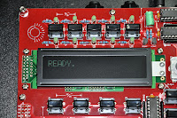
So when that done it was time to put the power on it and see if it actually was doing anything :) After switching it on you can see in the picture on the right that it worked. It shows 'Ready' in the display. Telling that the MIOS operating system is running on the PIC. It is kind of like the BIOS of a PC, but not the Operating System yet. Through this MIOS system you can upload software in the Midibox based synthesizer and that software determines its functionality. So that will be the next step in the next post. So far so good :) Still no smoke ;)

13 November 2011

Virtual DIY Project (Part 2)

Last night I worked some more on the PCB. I downloaded some of the components you see here, but also designed some of them myself. I'm quite happy actually about the blue Bourne trimmers I created. So slowly but surely I'm filling the PCB. I also had some work on bending the legs of the components. I ended up using the bend deformer in Cinema 4D. Great stuff once you understand how it works :)

And here is the project again a step further in completion. Now I also added some header connectors and capacitors. I also made the ceramic capacitors (brown) and polyester capacitors (red) from scratch. As you can see the three modules on the PCB next to each other are identical, so it was easy to copy paste them. I only had to make some minor adjustment to the placement of a few parts.

And here is a complete overview of the whole PCB, so you can see how far I'm into the project now. You can click on all the pictures for a bigger version by the way. I still have lots of work to do, but it is so much fun that I seem to lose track of time when I'm working on it. I can't wait to start animating it. I think I have most necessary components now, so for the major part of the projects it will be copying components and placing them in the right spot. More coming soon :)

Anatek SMP-16 Manual

The Anatek SMP-16 is a very versatile automated Midi and Audio patch bay. I have two of them in my studio and I love them. They are noise free and you can patch from the menu on the front and even save presets. It is an ideal studio tool. (If you have one on sale let me know because I'll buy it from you). It is just impossible to find a manual online apparently, since I had a lot of questions about it already in the past. I was lucky enough to get a manual on paper and even in English :) So today I decided to scan it and share it for anyone else that is looking for it. Since the company is bankrupt for years now I guess they won't mind me putting it online ;)

You can download it here:  http://www.synth.nl/files/Anatek%20SMP-16%20Manual.pdf

SammichFM (Part 4)

The next step in the building of the SammichFM is to solder all the components on the front panel PCB's. In this picture you can see all the IC sockets, switches, transistors, resistors and capacitors already on the PCB. Actually this is a quite straight forward job. Only on the bottom two right switches you have to cut the leads very short, because otherwise they would touch the heat sink of the power regulator on the base PCB when the whole synth is assembled. Something not to forget.

Then you have to put some spacers on the PCB again. This time to put the front panel in place in order to solder the leds in place. By putting the front panel on, you can stick the leds through the holes simply by turning everything upside-down. Then the leds fall into their intended positions. Because the whole thing is upside-down the leds can't fall out anymore and you can solder them on the bottomside. A simple trick but very effective. Everything looks good.

After this the PCB's are done and it is time to do some power tests, just to see if there are no short circuit. Everything turned out OK, so I put in all the IC's. Basically the electronics part of the project is done now, so it was time for the famous 'smoke test'. I put power on the construction while holding the upper PCB up so that nothing touched each other. And they after applying power feel the IC's to check if they get hot. Well no temperature and no smoke. So all looks great.

And here is a final picture with both finished PCB's. So far I still filmed the whole process and I'm into 3 hours of film by now. Which means I build the whole thing effectively in three hours, but of course over a period of a couple of days. Usually I spend about an hour a day working on a project like this. The next thing will be to assemble the whole case and test the synthesizer. I'm very curious if it will work of course. I'll let you know soon!

12 November 2011

Virtual DIY Project (Part 1)


I currently also working on a virtual DIY project. I'm making some video's about my DIY projects and I want to make a nice intro for that. So I started looking for a nice 3D model of a PCB on the internet, but I could not find anything I like actually. So I decided to make on myself. I started out by taking high res pictures of an EFM Wild Cat PCB that I still had laying around. At the moment I'm creating, downloading and adjusting the components. The idea is to fill the whole PCB. That will be a lot of work I can tell you, so it will take a while before I finish this project. I'll post some updates on the progress on this blog from time to time.

11 November 2011

Synth.nl visits Sea World 2011 Video

This video was initially made for a lecture at school of my youngest daughter about the Killer Whale (Orcinus Orca). On my OceanoGraphy album I also did a track about this magnificent animal called 'Orcinus'. I put that track under this video. I decided to put this video online to promote my OceanoGraphy album that was released in 2009 by Groove Unlimited.


Last summer we visited Sea World in Florida USA with the whole family. I wanted to show these magnificent animals to my kids, of course I'd rather have shown them in the wild, but that is almost impossible. I shot all the video with a little mobile camera from the audience. I made the animations in Cinema 4D. More information on OceanoGraphy here: http://www.synth.nl/OceanoGraphy

SammichFM (Part 3)

Next up was installing all the electrolytic capacitors. You have to pay attention here since their orientation matters. One leg is clearly longer than the other and the long leg is always the + (positive) side. In this picture you can see a little pile of them (green) between my tools. Maybe a nice moment to point out that is is the minimum of tools you would need for such a project: multimeter, cutting pliers, holding pliers, de-solder pump,some screw drivers and a soldering iron.

Here you can see the capacitors already on the PCB. As you can see most of them lay flat, so you need to bend the legs for those, and two are mounted standing up. On this picture also the connectors are already installed: Two midi connectors, two audio jacks, a power connector for the external 9V power supply and a Commodore 64 style power switch. On the front right is also a crystal install. I did solder that too quickly so it is not so neat on the PCB, but it'll work.

The next step is a tricky one. You have to install the big power regulator with two heat sinks. The whole construction has to be put on top of each other with heat pasta in between. That stuff is nasty and stick to everything, so you will have to practice the assembly first without the pasta and when you got the hang of it you do it one more time with the pasta on and try not to get it on your hands, cloths and the rest of the PCB. As you can see I did OK ;)

And then it is time to fit the LCD display on the front panel PCB. For this you have to put the spacers between the PCB's and put the connectors in place. Only like this you can solder them in the right height. The tricky thing though is that you can solder the connectors on the base PCB from the bottom, but you will have to solder the rest from the top, since you can't reach the bottom of that PCB this way. Once everything is soldered you can cut the leads and take the whole construction apart again.

10 November 2011

SammichFM (Part 2)

The next task in building the SammichFM was to install all the resistors. As you can see they are all 1% resistors and I always find it challenging to read the color codes on those. You easily mistake a 1K for a 10K resistor, so I tend to measure them all with a multimeter. Just to be sure. Luckily the resistor values are written on the PCB of the SammichFM, so it is easy. So measure a resistor and look for it on the PCB. You don't even need a part list for this process.

After the resistors it was time for the IC sockets Nothing difficult about that. The only trick I always use is to hold them with one hand with the PCB up-side-down and solder just one pin on the edge with the other hand. Then I look if it is in straight and if not I reheat just that one pin and readjust it. When you have already soldered multiple pins that is almost impossible. Then I solder the diagonal opposite pin (furthest away) and check again. After this you can solder the rest, since the socket can't move anymore.

Then it was time for the capacitors. And also a ferrite bead, a crystal and two diodes. Especially for the latest two you need to pay attention because their orientation matters. So far all the components are very flat and in this way you can easily roll the PCB over and solder on the bottom side. This, of course, is also the reason why you should solder in your components in this order. If you start with the highest components you lose this advantage.

And here a final picture of the OPL3 chip more up close, just because I thought it was a nice picture :) You can also clearly read the text on it. The PCB is full with little 'Easter Egg' jokes by the way. Wilba must have been in a very funny mood when he designed it, but I enjoy them while working. Not everything in life has to be so serious. I'm also still filming it all and it looks like I'll have enough nice material later on. In the mean time I've put my camera on permanent power, so that an empty battery won't spoil the fun again. Next post coming soon!

09 November 2011

SammichFM (Part 1)

Today I started a new DIY project as well. I'm going to build a SammichFM synthesizer. Like the name suggests it is a sister of the SammichSID, but this time not based on the Commodore SID chip  but on the Yamaha OPL3 chip (also know as YMF262). This was also a famous sound chip from the 8 bit computer era. It is a 4 voice stereo FM synthesizer. It was used on several famous sound cards like the Sound Blaster Pro 2.0 and the Sound Blaster 16 ASP.

The first task in building this kit is right away the most challenging one as well. The sound chip and 4 other components are so called SMD components. SMD components are surface mounted which means they don't have leads sticking through holes in the PCB, but they rest flat on the PCB and you have to solder the pins to pads on the PCB surface. These pads are very small and very close together. I did need my glasses for this and a magnifying glass to check if I did everything right afterwards.

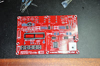
Wilba was so nice to put some flux in the kit to help improving the flow of the solder. That made things a bit easier. I did solder some pins together though. (It is almost undo-able not to make this mistake by the way) So you need some means to remove excessive solder as well. I used my de-solder pump for this. But in the end I got it right. In the picture on the left you see the remaining parts that I still have to put on there. But those are all conventional 'trough hole' components, so that should be a lot easier :)

Next to taking picture for my blog, I'm also filming most part of the construction of the SammichFM. So hopefully I can show you a nice video as well when it is done. Only during my work I'm not paying much attention to the camera of course and today already the battery ran out during filming and I didn't see that until after I had put on all the SMD components. I just watched how far it filmed and I have enough I think to show the process, even though I can't film to close but I guess you'll get the idea. OK enough for today. I'll continue this project soon and I will post updates on this blog from time to time.

SammichSID Repair

Today I heated up the solder iron again. It was a really long time ago that I used it due to all kinds of other projects. The first thing I wanted to do today is repair the SammichSID. I had been laying disassembled on my desk for a long time and I always worry then that parts might be lost. I found out earlier that it was behaving strangely because two leds didn't function properly. Actually this is the first time in my life that I encountered leds being broken, but apparently it can happen.

Luckily I was able to buy the exact same leds on E-bay from a shop in Hong Kong. Otherwise I had to replace them all. First I cut the leads of the old leds and tested them while out of the PCB. They still didn't work so my diagnose was right. I de-soldered the cut of leads from the PCB and then put in the new ones. After that I tested it and everything was fine :) I also upgraded the SammichSID to the latest OS and then couldn't resist playing on it for a while. The sound coming from those Commodore SID chips is still something special for me :) OK. At least I could take one point of my todo list again today :)