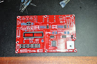
The next task in building the SammichFM was to install all the resistors. As you can see they are all 1% resistors and I always find it challenging to read the color codes on those. You easily mistake a 1K for a 10K resistor, so I tend to measure them all with a multimeter. Just to be sure. Luckily the resistor values are written on the PCB of the SammichFM, so it is easy. So measure a resistor and look for it on the PCB. You don't even need a part list for this process.
After the resistors it was time for the IC sockets Nothing difficult about that. The only trick I always use is to hold them with one hand with the PCB up-side-down and solder just one pin on the edge with the other hand. Then I look if it is in straight and if not I reheat just that one pin and readjust it. When you have already soldered multiple pins that is almost impossible. Then I solder the diagonal opposite pin (furthest away) and check again. After this you can solder the rest, since the socket can't move anymore.
Then it was time for the capacitors. And also a ferrite bead, a crystal and two diodes. Especially for the latest two you need to pay attention because their orientation matters. So far all the components are very flat and in this way you can easily roll the PCB over and solder on the bottom side. This, of course, is also the reason why you should solder in your components in this order. If you start with the highest components you lose this advantage.
And here a final picture of the OPL3 chip more up close, just because I thought it was a nice picture :) You can also clearly read the text on it. The PCB is full with little 'Easter Egg' jokes by the way. Wilba must have been in a very funny mood when he designed it, but I enjoy them while working. Not everything in life has to be so serious. I'm also still filming it all and it looks like I'll have enough nice material later on. In the mean time I've put my camera on permanent power, so that an empty battery won't spoil the fun again. Next post coming soon!


No comments:
Post a Comment