

 The problem is though that the Big Ben is literally the heart of my studio since it provides a clock (heart beat) for all the digital equipment in my studio, so I didn't want to take it out just for this, but today I was moving it anyway. And that is quite an undertaking since 6 separate Word Clock busses are connected to that and when you move the box you also have to move the cabling and of course after that you end up with some cable that are too long and some that are too short :(

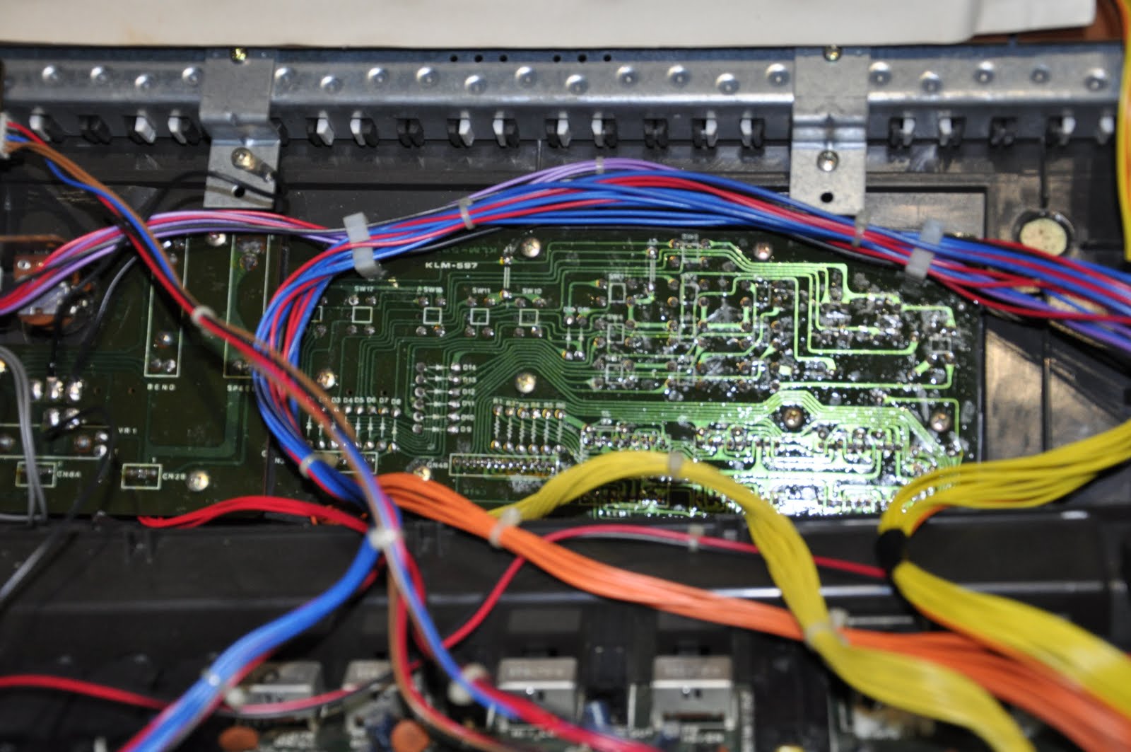
 So I just re-apply the same settings and it works again. I mailed with Eventide tech support about this and they had no idea. The only tip they had is to open it up and check the battery and reapply all the mechanical interconnects, like connectors and IC sockets. Well and today also the jog shuttle stopped working. So today I decided to have a look at it. I took it from the rack and opened it up. Well in the picture you can see a H8000 from the inside. The Battery was under the ADAT interface, so I took that out first. And measured the battery. It was 3 Volts like it should be.
 Anything below 2.8 Volts could be a problem they said and that is obviously not the case. I decided to remove the battery for a while to make sure the memory was completely empty. And then I reapplied all the mechanical connections, just to be sure. After that I put it back in the rack and reconfigured it again, turned the power off and unfortunately the problem was still there. I have no idea what else I could do myself about it, so I guess I'll have to ship it to them for maintenance. I hope they can fix it. I'll keep you posted.
 I have had a Waldorf MicroWave in my studio for a long time. It is a very nice digital wave table synthesizer with analog filters. It sounds really sweet, but my friend Hanz told me that it could sound even better. I still had the old OS Roms in there. So he pointed me to some Roms on E-bay that I could buy to upgrade it. Well actually I had these roms in my drawer for months already, but today I decided that it was time to finally install them into the MicroWave. So first thing was to get it out of the rack. Luckily the cables are long enough to even be able to test it this way.
 And here are the new Roms. They are just normal Eproms so I guess when you have the software and an Eprom burner you could just burn them yourself, but I'm sure you can also find someone on E-bay that still sells them. As you can see mine came shipped in a nice antistatic box with some antistatic foam. There are two E-proms one is marked H for High and one is marked L for Low. I guess you can't go wrong there. So it was time to open up the Microwave. Opening it up is quite easy. You just have to remove 5 screws and you can lift of the top cover.
 The Roms are in the upper left corner. I removed them using a small flat screw driver and my Roms were also marked H and L so that didn't require any puzzling. You just have to watch the oriention of the Roms. When I picked it up by the way I heard something moving inside the MicroWave and when I held it up side down a screw fell out :( I guess I was lucky that this screw never caused any short circuit. Well after screwing the lid back on I powered it up and it said version 2.0 so that looked good :) And then I put it back in the rack and played a bit on it. I think I will have to look up some new presets for it, but I'll ask my friend Hanz about that. Well another thing to scratch of my to-do list :)
 The last week I was having an annoying problem in the studio. I use a lot of digital effects equipment and they all need to be synchronized. To do that you can use a Word Clock bus. One machine in the studio is a master clock generator and the other equipment slave their clock to that. You use a BNC coax cable to connect the equipment to this bus with T- or Y- connectors like the ones in the picture. On both ends this bus is terminated with a 75 ohm resistor. All nice when it works, but when there is a bad connection somewhere in this loop you get cracks and hickups. Usually when I had this I moved the cables a bit and it worked again for a while but today I decided to go and track this problem down. So armed with some new BNC cables and connectors I crawled behind my desk.
 I found the problem quite quickly. In total I have 6 Word Clock busses originating from a Apogee Big Ben. The Big Ben has leds on the front that show the status of the loop. Since the led on loop 1 was going on and off each time I knew I which loop I had to check. It turned out to be the T-connectors I used on my RME interfaces caused the problem. Since they are just 1 unit high there is not much room on a T-connector for the cable. They are attached to the side. I replaced those T-connectors by Y-connectors that have the connections on the back. So here the cable goes straight out. The result is that there is no stress any more on those cables.
 After this I didn't see the led blinking any more and I worked all day in the studio. So I guess the problem is fixed now. Quite a relief actually, since I am working on finishing a track for a sampler CD that has to be done next Friday. Well actually I had to be ready today even since it needs to be mastered before I can send it in and we will start working on that tomorrow. My work is done on the track now. Hopefully they will select it and if they do it will be released in August. I'll let you know as soon as I know myself. For now I'm going back on working on my new album for October.
 When I'm in the living room I often work with my headphones on, listening to some music. I have a pair of closed headphones for that so that my surrounding isn't bothered by me and vice versa. Usually I prefer open headphones btw, but anyway there was a lose wire in the somewhere because sometimes on one ear I lost sound and when I fiddled with the cable it worked again. So I decided to take it apart. One of the wires was loose on the plug, but the wires were to short to solder them back. So I extended them for about a centimeter, put it back together and it works perfectly again :)
 I had a very annoying problem with the second PC in my studio. This is not my main audio recording PC, but a PC that I use for video stuff, mastering stuff, sample editing and also some editors for synthesizers are running on it. It is nice that I can do stuff on there that doesn't interfere with recording. But recently it became very slow and after a while it completely froze. It lost it BIOS settings on restarting. I was thinking it was time for a new one, but I decided to have a look first. So I detached all external USB and firewire connections and started removing PCI and PCI-e cards on by one. Suddenly when I removed one of my USB PCI cards it worked fine. So this card probably messed up the PCI buss on the main board. Well I'm very happy that I can use it normally again :)
 During the last year I bought some Synth modules from E-bay, but I didn't have time to test them yet. One of them was this LFO module. I hooked it up to my newly build power supply and was a bit surprised that the led on the front panel didn't work. I hookup the output to my oscilloscope and there was signal coming from it, but it looked very strange. Like a 50 Hz hum added to all the outputs. When I studied the module closer I found it to be a MFOS VC-LFO (Music From Outer Space) with an Oakley front panel. I found the schematics quite quickly online. Isn't the Internet great for that? :) You can find almost anything on there in just a few second. I love that :) I can remember the old days where this would take weeks or even months.
 The first thing I did after that was hook one of the power distribution boards that I got from MOTM to my lab power supply. Measuring on a live circuit always gives the risk of accidentally short circuiting something and this power supply is protected for that. You can also limit the current that can flow so nothing will burn out in case of a problem. The first thing I focused on what why the led didn't work. I put power on the led directly and it lid up, so it wasn't the led itself. One side of the led was connected to the PCB and the other side to the ground. Well I thought it was. Because after some tracing of the front panel wiring I found out that all the grounds were interconnected but there was no actual ground connection to the PCB.
 So in the end I just soldered a wire from the front panel ground loop to the PCB and that didn't only solve the led problem but also the other problems I saw with the signal. After that I had a very stable output signal on all connections. In the documentation was also a calibrating procedure so I did that as well. It cost me a good part of the afternoon to solve this, but it always feels very satisfying when it works in the end :) Here you see another picture of the VC-LFO module hooked this time to the new dual power supply I build this morning. On to the next project :)
 Last year I bought an Kurzweil Mangler FX processor and fell in love with one of the presets called 'Laserverb'. My friend Hans told me that I should look for a Kurzweil KSP8 then, because it has much more power and much more effects on board. I found a very nice set including an ADAT board installed and a remote controller and even an extra 8 channel AES board. When I hooked it up I couldn't get it running though. It worked on the Analog inputs and outputs and also the AES port worked, but I wanted to hook it up through ADAT to be able to use all 8 channels on it. It started already at the fact that it didn't want to sync its clock to the ADAT input. That gave me the impression the board was broken. Then I installed the AES board and everything worked fine. I decided to give to board a closer look and to my surprise I found a loose soldering just at the optical receiver for the ADAT input. I resoldered the whole connector put it back and it worked :) And boy is this thing nice!
 Here you see a picture of the remote that came with it. A very convient way to control the unit. There are 8 rotary knobs on it to adjust the effect parameters and also a joystick to do some nice modulation stuff on some of the presets. I played around with some of the presets today and the KSP8 sounds awesome I can tell you. Especially the freaky stuff you can get from it is amazing. And having 8 channels is great. You use them as 8 x mono, 4 x stereo of even 5.1 surround. There are even surround presets in there. The KSP8 is being dumped for low prices everywhere on E-bay (even new). I can recommend it to you if you like good sounds effects. Only the ADAT and 8 channel AES boards are harder to come by. But if it is out of your budget look for the cheaper Mangler or Rumour from Kurzweil. My Mangler is going for sale soon by the way because the KSP8 out powers it by far.

 Posts
Posts