03 November 2009

Yusynth (Part 10)

I also had a very productive afternoon. I actually finished another Yusynth module. Well almost but I will get to that later. I worked on another filter module this time a Minimoog VCF also called transistor ladder filter. This is of course a copy of the famous Moog Minimoog filter design. It is build around two CA3046's and 6 BC547 transistors that have to be matched in pairs. In this picture you can see the PCB where I already soldered all the wires on again. Behind it is the front panel with all the front panel components mounted already. I did this long ago already. So all I had to do today is wire those to the PCB.

But first I needed to drill the holes in the bracket that is attached to the front panel. I told you before that the steel that the bracket is made of is very hard and I couldn't drill holes in it without breaking something. Well here is the drill that I bought that solved that problem. I got it quite cheap at a building material store and it is actually very good and solid. I have it standing in my garage now on my other work bench. There I do all mechanical stuff. If you look in the right on the picture you can also see a Ferrari Radio Controlled car. I enjoy driving those too, but it has been a long time. But I usually work on that sort of stuff on this work bench.

OK back to the filter module :) Wiring this thing was quite easy, since it looked almost the same as the previous filter module I build. The only problem is that I was missing one mounting nut for one of the potmeters. You can see the hole for it and the loose wiring in the picture on the left. I already asked Scott from Bridechamber to ship it with the recent order I did. So I hope to get it soon. This potmeter controls the CV2 input. So it is not really a problem since I can easily test the module with the other two CV inputs. I will mount the potmeter as soon as the nut arrives.

I used the same method to test this filter module. And it was working right away. I did need to do some calibrating on the potmeters on the PCB again to get it to self-oscillate. But other than that I encountered no problems on this one. It does sound very different though from the EMS filter. Much warmer and softer even the tone you get from the auto oscillation is softer. Well that was supposed to happen :) So all's good. I have another working filter module. I think that was enough DIY modular work for today. So now I'm going do to some other stuff. Hopefully I will have time soon to finish some more stuff. I'll keep you updated of course!

Yusynth (Part 9)

This morning I finished another Yusynth module. This time it is an EMS clone filter also called diode ladder filter. You can see the diodes on the left top corner of the PCB. The values of these diodes are critical and need to be matched. You can measure the voltage drop over the diode. Typically that would be 570-590 mV. But I had to select 14 that where within a range of 3 mV of each other. I did this by measuring them and writing the value on a big piece of paper and then put it on that value. Then the next one and so on. Until you end up with 14 on one spot or just one above or below.

I had the PCB ready already, except for the diodes. So after matching them I soldered them to the PCB. After that I started with the wires for the front panel components, leaving them long enough to be able to reach every front panel component later on. And then I started doing the wiring that connect the front panel components together. You can clearly see this in the picture on the right. Here you can also have a good look at the bracket that will hold the PCB later on. Bridechamber came up with a great idea for that. Just use the potmeters on the front panel to hold it in position. I wanted to use blank wire btw for the ground, but for some reason the electronics shop where I usually get my stuff from just doesn't have that anymore. Well no disaster but blank wire is always easy for hooking up the ground of the oscilloscope later on while testing.

In the picture on the left you see the finished module from the back. Now you can see why I always leave the wires on the PCB so long. In this way you can nicely bundle them together so that it becomes a nice cable tree. Is that important? Uhhhh no not at all. but it just looks better ;) On the bottom you can see the screw connector that I use for the power now. I actually works quite well. I just ordered some female MOTM style power connectors from Bridechamber that I will attach to this connector so that I can easily hook them up to the MOTM power distribution boards.

After that it was time for some testing. After the usual smoke-test I hooked one of the inputs up to a noise generator from an Oakley module. The cut off potmeter did its work quite nicely, so the filter worked, but on the resonance potmeter I didn't really get any noticeable result. So I started to check my wiring and measure if it did what it was supposed to and it did. But no result. So I started to look at the schematics and when I was just doing that I read a note from Yves that this could happen. It had to do with one resistor that determines the range for the resonance. It had to be changed from 680K to 220K. Well I didn't have a 220K but I soldered two 100K's in series to get 200K and that did the job nicely.

After I changed the resistor it started to auto oscillate as well. And man does it sound nice on that :) I hooked it up to an LFO module to generate some nice sound effects with it. In the picture on the left you can see the finished module from the front. As you can see it even has two audio inputs and the frequency and resonance of the filter can be controlled with CV signals. You can even tune the auto oscillation to do 1 Volt per Octave, so that it becomes a real oscillator. Yves says it will track over a span of 3 Octaves. But you need to calibrate this with a trim potmeter. I haven't tried this yet. I will do that in a later stage. To be honest I don't think that I will ever use it like that . But it is nice that it can. All in all another nice result this morning. Let's go to the next one :)

02 November 2009

AVRSynth 32 (Part 2)

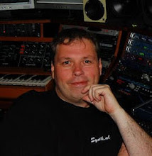
After dinner today I went back to my modular desk for some more soldering. I asked my daughters if they wanted to join me in the studio since my wife had to go away and they were quite happy about it. Here you see a picture of me that my daughter took when I was soldering a whole bunch of diodes. And yes I'm wearing glasses. My eye sight is actually fine, but they have prism glasses that make it easier to focus. When I'm working long time my eyes don't get tires. And since there is not that much light down stairs my eyes have to work harder anyway. During soldering I tried to explain to my daughter also how a diode and a capacitor works. She says she understands it, but it is a bit difficult for me to believe. But I will try and keep explaining stuff to her. She seems to be very interested.

When we were busy my youngest daughter came to the studio as well. Dressed up as Minnie Mouse with the ears and all :) Isn't it sweet? Well now my oldest daughter is starting to explain to the youngest one what everything is on the PCB. I think that is so cool.
Well after that we continued to solder all the capacitors to the PCB. We could not find one of the capacitors but when I reread the documentation it turned out that this one needed to be soldered to the bottom of the PCB just like the resistor we couldn't find earlier.

Here is a picture of how far we got today. As I said before my daughter is quickly loosing concentration. So the PCB still is not finished. You can also see some drawings that I made while trying to explain what everything does. It is really fun for me to since my whole school period is passing by me :) And even though I used to hate it back then now I think it is fun. Life is weird right. I still haven't counted the potmeters on the ASM-2 by the way. So I still don't know if they are missing from the AVRSynth. Ah well I can't do everything at the same time. I'm doing a lot already I think.

After soldering the girls wanted to jam a bit on some synthesizers. Here you see them play on my Korg M3. Today they discovered Karma and how much fun that is. It didn't sound very harmonious, but it was nice that they played without fighting over it. That is harmonious as well right? :) They were quite lucky too because with all this fun I forgot the time and they were in bed half an hour later than usual. I have seen a lot of trick to stall before then go to bed, but this one was even new for me ;)

Yusynth (Part 8)

Today I finished my first Yusynth module. I started this project long time ago, but I picked it up again. The module I worked on is a dual module. It has a noise generator with pink and white noise and it also has a random and sample & hold module. Here you see the PCB in front where I soldered all the wires on first. And in the back you see the front panel I got from Bridechamber with the front panel components already on there and also the bracket where the PCB will be mounted on. If you look closely at the PCB you can also see a transistor in a socket. This transistor is easily swappable this way and that was necessary to later on select a transistor that creates the best noise :)

Soldering the wires to the front panel components on Yusynth modules is quite easy. Yves gives very nice wiring schemes on his website. I mounted a little screw connector on the PCB for the power. Since I don't have any MOTM style power connectors I just screwed the power on the power distribution board. Here you see the finished module, only the led is still hanging loose. I need to find a nice led holder to mount it on the front panel. After hooking the power up I first did the elementary test for smoke and hot components and that all looked fine.

After that I hooked up the module for testing. First of all I tested the noise sources directly on the audio and swapped some transistors. But actually I didn't really hear a difference. Both sources sounded great to me. After that I hookup the module to the VC-LFO I repaired earlier. I used it as an oscillator actually. And also the Random and Sample & Hold worked fine. Then I tested the external input and external clock. And almost boring that worked as well. So I have a fully functional Yusynth random module now. If you are interested in this module. You can find more information about it here: http://www.yusynth.net/Modular/EN/NOISE/index.html

Quest For Leak Continues

Last night it leaked again. When my wife looked in the studio this morning because it rained quite heavy last night and there was water again in one of the buckets. So it leaked again. I immediately called the constructor and he came right away again. It was dry when he came, but we put a couple of buckets water in the hole and it started leaking again after a while. So now at least we are quite sure it must be still coming from this same place. But the frustrating thing is that you don't see anything happening at all.

The constructor tore down even a larger part of the wall to make room for an even bigger patch. This time though we will not remove the old one, but just put it over it. It has to stop one day. I'm very tired by now of this. You just can't leave the house when you know it is going to rain. Well in this picture you can see how far our wall is destroyed now. But I'm sure that will be fixed again. Lets first fix the problem. Hopefully tomorrow they are going to apply the new patch. Until then I can only hope it will stay dry. I will keep you posted as always on the progress.

01 November 2009

Terry Hawke Interview Online

Last night I did a very nice interview with Terry Hawke on his Halloween special for his show on Harborough FM (HFM). It was broadcasted on radio and also on the webstream. We talked a bit about Halloween to start with, but after that we talked about my new album release, my relationship with the Word Wildlife Fund and also about the future projects I'm working on. It was a very nice and relaxed interview that you can still listen to in case you missed it. I saved a copy on my website with kind permission of Terry and HFM. You can find it here along with some older interviews I did:

http://www.synth.nl/interviews.php

31 October 2009

Radio ARA Interview Online

During the E-live festival in Oirschot where I released my 'OceanoGraphy' album., I also had a stall there where I sold my CD's. I was visited there by Gaston Klares of the Luxembourgh radio station Radio ARA. We did a nice interview there that was recently broadcasted. I was able to record that part of the show from the webstream. You can also hear two songs from the album that are not on the player on my website. You can find a copy of the interview here: http://www.synth.nl/interviews.php. Also my other interview are still online for your to enjoy. I hope you like it. Tonight I will do another live radio interview by the way. I will try to record that one as well.

First OceanoGraphy Reviews Online

Yesterday I received the First review of my OceanoGraphy album by Bert Strolenberg from the website Sonic Immersion. You can find a direct link to the review here: http://www.sonicimmersion.org/review.php?letter=S&review=71888. When I looked on the Groove Unlimited website I also found another review by Paul Rijkens. You can find that one here: http://www.groove.nl/cd/g/gr-164.html. You can also leave your own review here if you like. I also placed a copy on my own website on this URL: http://www.synth.nl/reviews. I will put future reviews on there as well. You can also read the reviews of my previous albums there. Well so far reactions are very nice :)

29 October 2009

Servers Moved to New Datacenter

Today I moved my servers that also hold the Synth.nl website from Datacenter BIT-1 to Datacenter BIT-2. Actually the physical move was done by Peter and Eelco from BIT. We started at 10:00 this morning and the servers were fully operational again at 11:00. So they did lightning fast work. Thanks for that guys! But then the trouble started. I run VMWare ESX on the two Sun servers you see in the picture. I though this was a nice opportunity to upgrade from ESX 3.5 to 4.0 right after the move, since everything was down for a while anyway. But then the black Intel machine on top of the Suns didn't work anymore. I had to completely reinstall it. And that machine was running the Virtual Center tool that manages the two ESX machines. So I could not get my Virtual Servers running. And after the reinstall of the machine it turned out, after a long time of trying to get it to run and phoning VMware support, that there was a problem with my licenses :( A nice Indian support guy helped me with at temporary license, but it took until 15:00 before I had my virtual machines running again. Ah well that's life.

Tomorrow I will have to do some more work on my little platform and will call the reseller that screwed the licenses up for me. I'm sure I will get it right eventually, but it was a lot of lost time for nothing. If you are asking yourself by now if all those servers are only for the Synth.nl website. Uhhhhh no not really. There is a lot of other stuff running as well. It is quite a nice platform that runs several virtual Windows and Linux servers. The nice thing is that the data of all the virtual servers on this platform is actually stored on a redundant NetApp cluster from BIT and I can easily move an virtual server to another physical server if necessary. And now I also have redundant power feeds in BIT-2, better cooling and easier access to the servers. So it was worth the move for sure. If you are looking for a datacenter in The Netherlands by the way be sure to check BIT-2 out :) It is really state-of-the-art. Do contact me if you are interested. Well enough for now. I hope you didn't miss my website for too long ;)

28 October 2009

AVRSynth 32 (Part 1)

Two days ago my oldest daughter had her 9th birthday. And since she is very interested in music, synthesizers and music I decided to give her a special gift. She got her first DIY Synthesizer project. It will become a AVRSynth 32 and it came as a complete kit from Elby Designs in Australia. She is very proud of it. We will build this one together and I will only work on it when she feels like it. But today we already started. First thing we did is see if all the components were present and it looked like some stuff like pot meters and switches are missing. But I also got the front panel components for the ASM-2 so maybe they got mixed up.

We started this nice father-daughter project today with the PCB. It is a digital synthesizer based on a ATMEGA32 8 bit microcontroller running on 16 Mhz. So actually it is a little computer. So the electronics are actually not that complex. We started by mounting the IC sockets and the resistors. Elby has everything nicely bagged and labeled by the way so you don't have to look long for a component of a certain value. My daughter looks up the components and the position it is supposed to go on the PCB and I do the soldering. She sees it like a big puzzle.

Here you can see how far we got today. All the resistors are in place now. She was already tired after this so we decided to stop. I guess we will continue this project soon. The nice thing is that she was very fascinated how the soldering works and I even managed to explain to her how a resistor works. I hope she keeps this enthusiastic about electronics, because I much rather do this kind of stuff with her than play with dolls ;) I'll update you soon on this project again. And now I'm going to count some ASM-2 front panel components.

More Screens in the Apollo Studio

I'm also working on finishing the studio. Since I'm planning to start working more with video I added some more screens. They have HDMI input and can project a 1080p full HD picture. Besides this it is nice to play a video on there while I'm working. I actually did this during the production of my 'OceanoGraphy' album to get in the mood. I watched a lot of Nature Documentaries without sound while I was composing or producing. I also watched some other movies in between when I was resting my ears. I played those movies from an Eminent player. And yes I have them legally ;)

As you probably know we also build a cinema while constructing the new studio. We bought a full HD beamer for that, but we had a beamer in the living room before that. I recently removed that from the ceiling in the living room and mounted it on the ceiling of the studio. It is not HD, but I will be nice to work on multi media projects on that for sure. I need to figure out now though how to hook up all this video stuff to be able to easily switch between it all. But I'm sure I'll find a solution for that.

So how does it all look. Well great I think personally :) And no I don't have everything switched on all the time. The projection screen for the beamer is electric. So I can roll it up and down. I'm still not done in the studio. The next thing to do is get surround sound in there. I will use my old Behringer monitors for this. I have mounting brackets for them already, but need someone to help me out with this. As some of you might have heard before I'm planning to release some music in surround in the future and I want to start experimenting with that soon. I'll keep you updated on this as usual :)

Wogglebug (Part 2)

Today I finished the Wogglebug module I was building. I had some trouble drilling holes in the bracket that holds the PCB. It is some kind of very hard steel and it looked like it was as hard as my drills :) Now I bought a special set of super strong gold colored drills and with those it was no problem. After attaching the PCB to the bracket I started wiring the front panel components. Since there was no real construction manual I figured out what went where using the schematics I downloaded from the Internet. And then comes the always exciting moment of hooking the power up.

Well that all went well. The first thing to always check is if there is no smoke and if no components get really hot. I always switch the lab power supplies on with a very low current limit so that this should not happen anyway. But better safe than sorry. But OK. It all went well. Then I hooked up the oscilloscope to see if all the signals were coming out of the jacks and that all looked fine. The final thing I did was hook up a PC speaker to get some audio from it. And it started making weird noise right away. And that is what a Wogglebug is supposed to do :)

The final thing was to test all the functions. And only the 'cluster' function I don't understand. If someone can enlighten me please do :) But it is a very nice module. It is like a supercharged random module. I just called my two daughters downstairs to play around with the module and they had a lot of fun with it. I even managed to explain to them how sound is made en showed then on the oscilloscope what it looks like. Well for now I'm done with this module and I'm going to finish up another project. I have a lot lying around from last year.

Here is another close-up picture of the front panel. The only thing that is confusing in my opinion is that it is not very clear what are outputs and inputs. Actually there are only two inputs on the module: 'Clock' and 'Rate CV'. They can both be controlled externally. The rest are outputs were the upper row are CV outputs to control other modules and the lower row are audio outputs. So you can hook them right up to a speaker to get weird noises. Especially 'Ring Out' is nice since it is a ring modulated sound coming from it. Oh 'LFO out' is also an output and is actually the internal clock. When you connect a jack into the 'Clock' input it is overridden by the external clock you offer there. Well I'm going to play around some more with it and maybe will post some sounds later.

21 October 2009

First Synth.nl Apollo Studio Video (2009)


First shots from my new Apollo Studio. The music is a track called 'Atlantico' from my new OceanoGraphy album.

18 October 2009

OceanoGraphy Released !!

Yesterday I released my third album called 'OceanoGraphy'. My inspiration for this album came from the Earth's Oceans and the creatures living in them. While listening to this album you will be taken on a journey through the deep waters of our Oceans. You will travel together with whales, dolphins, sharks and sea turtles. Most of these animals are endangered or even threatened with extinction by the way! We should really care more about the life in our Oceans. I hope to get your attention for this mysterious world in this way. I would be a real shame to loose it for ever. This album is officially endorsed by the World Wildlife Fund (WWF) for this reason. A part of the revenue of this album will also be donated to the WWF to help preserve these beautiful animals. I sampled a lot of sounds again myself as well above as under water. This album was released during the E-live festival on the 17th of October 2009. The CD holds 12 tracks on it and is 73 minutes long. You can find more information about the album and also where to buy it on this URL: http://www.synth.nl/OceanoGraphy

16 October 2009

CD's in stock at Groove Unlimited :)

I just visited the website from Groove Unlimited and saw that the status for my CD was changed from 'expected soon' to 'in stock'. This means that they are done in time for the release tomorrow. I'm quite relieved about that, since it was all very tight in the planning. This also means that Groove Unlimited will start shipping soon for you that pre-ordered the CD. If you didn't order it already here is still your chance to be amongst the first to hear it:
http://www.groove.nl/jump2.php?attnum=6001
And of course you are even quicker when you pick it up tomorrow on my stall at E-live -> http://e-live.groove.nl. I'm looking forward to the release tomorrow :)

11 October 2009

Mooger Frooger Fun

After soldering today I though it was time to have some fun. So I hooked up the Mooger Froogers that are on my modular desk for a long time already, but I just didn't have time to even test them. From left to right you see the MF-104Z Analog Delay, MF-105 Murf and MF-103 Phaser. I hooked them up to the PAIA 9700S to get some sound. The analog delay is nice but quite straight forward, as well as the 12 stage phaser. They are nice, but not spectacular, but with the Murf I had a lot of fun. It is a filter effect with different band pass filters that gets switched on and of in different patterns. It is something like a multiband gated filter. You can really make nice effects with it. But all in all the Mooger Froogers are lots of fun and I think they complement the modular setup very well :)

Wogglebug (Part 1)

Today I worked a bit more on my modular project. I'm currently building a Wogglebug module. The design is made by Grant Richter and it was originally a Wiard concept I think. The whole purpose of this module is to produce unpredictable control voltages and sounds. Sort of a random module, but with some extra controls. I bought the PCB from the internet and got a front panel and components kit for it from Bridechamber. Soldering the PCB is not as easy as it looks. Even though it is a very small PCB there are some SMD components on there (Surface Mount Devices). They are very small and don't have pins that stick to holes on the PCB, but you have to solder them on top on a very tiny area. Well they are not all that straight on but I think it is good enough now. As long as everything makes contact it should be fine.

After that I started soldering wires to the PCB that will be attached to the font panel components later on. In the picture you can see the back of the front panel. On the left are the jack connectors for the inputs and outputs and on the right the various potmeters that will control the Woggle Bug when it is operational.
If you are asking why I used two different colors in the wiring, well I want to make two neat cable trees later on and this way I can seperate the cabling to the jacks and potmeters easily. That's all.

Unfortunately I haven't been able to find a nice building manual for this project so I'm figuring out what goes where from the schematics. I found them quite easily on the Internet as a PDF so I can look at it on my monitor just next to my workspace. Very convenient. I'm already happy that I put that computer there now. I'm quite sure I'll need this more often in the future. Well next task is drilling some holes to attach the PCB to the bracket attached to the front panel that will hold it in place. But I haven't got a decent 3mm metal drill. So I'll have to get one first before I can continue. The one I had broke this afternoon because I used to much force. Unfortunately I cut my hand as well in the process. Nothing serious though. Well I hope to continue this soon.

10 October 2009

EMPortal Spotlight for OceanoGraphy

I'm slowly starting up the promotion machine here for my upcoming album release. Just one week more to go! I did sent out some clips to some radio shows and here and there I already got some airplay. I hope more will follow. Besides that I'm sending out some announcements here and there. Today one was picked up on the EMPortal forum. Doesn't it look nice on the front page :) This is a very nice forum by the way if you are into electronic music like my own. Go and pay them a visit on: http://www.emportal.info/. If you know of any more places to promote my album. Please do! Any help in promoting is very much appreciated. I can't do it all alone :) So yes. Please help!!

08 October 2009

And it is leaking again :(

This is getting very annoying. Last night I was working at my modular desk wen suddenly some water dripped on my head. So I removed the cover again from the ventilation hole over me and water came pouring out :( So I placed the bucket again under it. I didn't really sleep last night because it started leaking on more on more places. Eventually the water was dripping down on 5 completely different places. I can't really imagine that it has to do with that hole that has been repaired twice now. There has to be some other leak as well I guess.

This morning the constructor came by again and we discussed the other possibilities of a leak somewhere else. Just reconstructing what happened during the whole construction process. I'm afraid more of our house is going to be torn down now. I feel really shit at the moment. Thus far I have been very lucky still that no equipment was damaged, but when ever it starts raining now I just can't afford the be away until we fix this for good. It looks like it is staying dry today. So maybe I can get some sleep later on. And I could really do with some GOOD news...

07 October 2009

MFOS VC-LFO Repaired

During the last year I bought some Synth modules from E-bay, but I didn't have time to test them yet. One of them was this LFO module. I hooked it up to my newly build power supply and was a bit surprised that the led on the front panel didn't work. I hookup the output to my oscilloscope and there was signal coming from it, but it looked very strange. Like a 50 Hz hum added to all the outputs. When I studied the module closer I found it to be a MFOS VC-LFO (Music From Outer Space) with an Oakley front panel. I found the schematics quite quickly online. Isn't the Internet great for that? :) You can find almost anything on there in just a few second. I love that :) I can remember the old days where this would take weeks or even months.

The first thing I did after that was hook one of the power distribution boards that I got from MOTM to my lab power supply. Measuring on a live circuit always gives the risk of accidentally short circuiting something and this power supply is protected for that. You can also limit the current that can flow so nothing will burn out in case of a problem. The first thing I focused on what why the led didn't work. I put power on the led directly and it lid up, so it wasn't the led itself. One side of the led was connected to the PCB and the other side to the ground. Well I thought it was. Because after some tracing of the front panel wiring I found out that all the grounds were interconnected but there was no actual ground connection to the PCB.

So in the end I just soldered a wire from the front panel ground loop to the PCB and that didn't only solve the led problem but also the other problems I saw with the signal. After that I had a very stable output signal on all connections. In the documentation was also a calibrating procedure so I did that as well. It cost me a good part of the afternoon to solve this, but it always feels very satisfying when it works in the end :) Here you see another picture of the VC-LFO module hooked this time to the new dual power supply I build this morning. On to the next project :)