27 February 2010

Surround Monitoring Setup

Last week I've been very busy in the studio together with Sjoerd from Sjoerd Productions who helped me to mount new speaker stands in the studio. I'm planning to work with surround sound in the future and I need a monitoring setup for that. I still had my old Behringer Truths that I used in my previous AtmoSphere studio. So for now I'm going to use them as my temporary surround setup. I hope to replace them in the future with digital Genelecs to integrate in my main stereo monitoring setup. But for now they will do I guess. I'm just going to do some experiments now.

It is a 5.1 setup with also a seperate subwoofer. In the picture above you see al the stereo front speakers. From left to right the Behinger, Avantones, Mackies and Genelecs. They all have their qualities and if my mixes sound good on all of them I'm sure they will sound good on your setup as well :) In the picture on the right you see one of the back speakers and you can also see the speaker mount below them. According to the manufaturer they should be able to hold 25 kilo and the Behringers are 15 kilo, but it sure looks like they have a lot to handle. I hope they hold.

In this picture you can see the center speaker. We mounted the center and surround speakers a little higher, since I'm also planning to replace them eventually with smaller speakers. I will leave the outer behingers then just for stereo (hifi) monitoring I guess. The speaker mounts are very universal since the speakers are not actually attached to them. They just stand on there, so I can replace them easily with different ones later on. Well now I just have to hook everything up to get some sounds from them. The cables are already in place but I need to solder connectors on them. The only problem is that the cables are not near my soldering iron ;) So I'll have to move the soldering iron to the cables this time.

25 February 2010

ASM-2 (Part 10)

I worked some more on the ASM-2 last week. I did some more work on the front panel components. This time I installed a lot of pot meters. The hardest thing is to figure out what goes where. There is no clear documentation on this only some suggestions from Elby Designs. I ordered a complete front panel component kit back then, but it looks like it isn't complete. I'm definitely some pot meters short and I found a broken one in the package. I also installed two push button switches for manual gating the ADSR's and three rotary switches that had to be limited to 4 positions first. Finally I installed some led holders where I changed the leds in some because I wanted different colors than were in there. I also switched the stereo jacks I had left from the last time.

And here is a picture of the back of the front panel. You can see there are still some components missing. Those are not all the missing pot meters. I still have some left, but not enough. What is also strange is that in the front panel the holes for the potmeters or VCA2 are bigger than on VCA1. I guess that is a design flaw, I can't imagine any reason why there should be different size potmeters there. I will e-mail Elby with these questions before I continue. It is nice to know what you are doing I guess :) And to be honest I'm done with it for now as well. This is not the job I like the most. Because the cabinet is so big it is quite difficult to hold a component on the front and fasten it from the back. I can feel some muscles now that I didn't know I had ;)

So after this I put the ASM-2 cabinet back on top of my modular desk. I still think it looks great there. But for now it is not doing anything but standing there. I hope I can get some life into it soon, but I still have a lot of other projects that I need to finish also that I think are more important first. Next week Gerrit my furniture builder is coming with the second extension to the modular desk by the way. I already let him know that some modifications must be made to the first extension. Most modules don't fit in there unfortunately. Ah well. We'll get that right eventually as well.

21 February 2010

OceanoGraphy wins Best CD 2009 Schallwelle Hörerwahl

Yesterday I went to the Schallwelle Preis awards ceremony. This price is organized by the German Electronic Music Club Schallwende. My OceanoGraphy CD was nominated by the Jury but also by the Listeners. And I'm very pleased to tell you that my OceanoGraphy CD actually won the Listeners price! And that is because of all your votes! Thank you very much for that. I see this as a big compliment and a great motivation to create more music. My congratulations also to the other price winners. And my thanks to the organizers of this very nice event. Price or not, I had a great evening! Hopefully I can be part of this again next year :) Thanks again for all your votes!!

((C) Picture by Thomas Wilberg)

18 February 2010

Yusynth (Part 25)

I finished two more Yusynth VCO modules. I got the front panels from Schaeffer again, but this time I corrected the mistakes I did on the first one. So everything fitted a bit better now. I used the first VCO I build a while a go as an example. That saves a lot of time. I used the same colors on the wires and the same routes as well. I think I build these two in about the same time that I build the first one alone. I also installed a MOTM style power connector on some nicely twisted leads as you can see. I did this for the existing VCO as well and decided I'm going to do all Yusynth modules this way.

After that I hooked them up to the lab power supply to do some initial tests. All looked well. Then I started with the calibration process. I didn't tune them yet, but I did the wave shape adjusting. On the oscilloscope you can see the output from the Sine Wave jack. This was as good as I could get it. I wondered a bit about the triangle wave. Those were not quite the same on the two newly build modules. But I will have another go at them when I am going to tune them. It was not that drastic by the way, but just some minor difference. Could be component tolerances I think.

I made one stupid mistake by the way. When I finished the first one of these two I put some cooling pasta on top of the tempco that is on the PCB and then I decided to put the cooling paste on the other one as well before I had wired it. Well never do that ;) You will hit the stuff with your wires or your hands and it is sticky. Another lesson learned today. Here you see a nice picture of the three Yusynth VCO next to each other. I still have one PCB left so maybe I will finish that one as well. I will have to order a front panel for that one then though. I'll let you know when I do.

Windows 7 on Solid State Disk

At the moment I'm upgrading the two PC's in my studio to Windows 7. I never delete my old installs since sometimes you really need to go back to them for certain files, so I had to buy a new disk for the both of them. I found out that the price on Solid State Disks have dropped dramaticly so I bought two 128 Gbyte SSD's. They are great since they have no moving parts, don't get hot and make NO noise at all :) The data for these machines will remain on a RAID1 set of normal disks for now. So I use these SSD's only to boot Windows 7 from and to install my software. I just finished the video/mastering PC in my studio with a 32 bits version of Windows 7 and reinstalled all software back on it. Everything seems to run fine. Next up is the Audio PC. I will go for a 64 bits version on that one. But there is a lot of software installed on it, so that will take some more time.

16 February 2010

Wilba MB-6582 (Part 4)

I finally sourced a nice Commodore 64 Power Supply for the MB-6582 from E-bay. Actually the shipping was more expensive than the Power Supply itself, but now I can finally continue. As you can see this is the newer type that came with the Commodore 64 II. I was a bit worried that this one would have different voltages or something like that, but I couldn't find an old type and I read everywhere that this type is more stable. So I decided to go for it anyway. In the worst case I could always look up an Commodore 64 II without a power supply ;)

Then I looked up the pinout of the power connector and hooked the power supply up to the mains power. I measured on the connector and it just have +5V DC and 9V AC like it should be so that was clear. Then I hooked it up to the MB-6582 base PCB and measured the power on the different test points on the PCB. Wilba advises to do this first before inserting IC's that makes sense. You don't want to blow up your precious SID chips. I measured +5V, +9V and +12V nicely where they were supposed to be so all was clear now to continue this project :)

Then I inserted all the IC's. I had some trouble doing so because I couldn't read all the text on the PCB silkscreen anymore. On the small IC's the text is actually under the IC sockets. So I looked on the MB-6582 Wiki for a silk screen picture, but couldn't find it. But luckily through Google I found a high-res picture that someone made of the PCB without components, so that helped me on. After inserting all the IC's I switched the power on again and nothing got hot and all voltages still looked great. So I guess so far so good. Next thing is to hook up the display and see if something happens. I'll keep you posted on the progress, but it is starting to become a synthesizer slowly but surely :)

Oakley Overdrive Module

Today I finished another Oakley module. This time it is an Overdrive module. Well actually you can switch between an Overdrive effect and a Distortion effect. I think these are the oldest effects around used to give electric guitars some extra punch and overtones. There are lots of guitar pedals around you could use for this as well, but Oakley made a nice 1U MOTM format module for it with two effects in one and of course it is more suitable for synthesizers. In the picture you can see that the wiring of this module is actually very simple. Just two jacks and one double pole switch to wire.

Well actually the whole module is quite easy and straight forward to build. There is no calibration to be done either. So after soldering the wires I hooked it up to the lab power supply to test it. I put a triangle wave on the input from the PC function generator. And if you look closely on the oscilloscope you can see an example what you can make from that. I haven't attached it yet to a sound source, but I believe what I see on the oscilloscope ;) I tested all functionality and decided it was done.

Then I put the knobs on and mounted it in my cabinet. As you can see there are three pot meters on the module. The top on is gain and that is on the input side, so with that pot meter you can determine how much signal is going in to the effect. In the middle is the timbre control that makes it possible to change the color (and so the shape) of the output signal and below is a dry/wet mix control. Which make is possible to regulate if you only want the input signal or add a little effect to it or by turning it all the way up you have the fully distorted signal. Then the switch to select on of the two effect modes and the input and output jack. All very straight forward, but a nice effect to have in the modular setup I think. Well that is all I can really say about it :)

15 February 2010

Synth.nl on Soma FM

Last week my music was played on Space Station Soma on the US Soma FM. They played the title track from my current OceanoGraphy album. I got an E-mail from Andre who pointed me to this. I'm very happy to hear such things, so please let me know if you see or hear my music played somewhere. I'm very happy with this airplay since Soma FM is quite big and they have listeners all over the world. Hopefully they will play me some more in the future :)

14 February 2010

Mr. Braska's Apollo Studio Experience (Part 6)

Here is the last episode of Mr. Braska to my Apollo Studio. Here he is hanging from the Klee Sequencer I recently finished before I started wiring it.

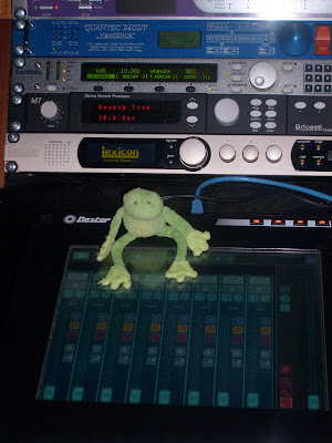
Mr. Braska was allowed to inspect the rest of the studio as well and this was his favorite corner. He just loved the Jazzmutant Dexter. He was staring at it for a very long time.

And here it was time for action. Mr. Braska made a nice bass line on the Arp Sequencer. Maybe you will hear it on some future album.


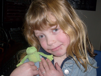
Here my youngest daughter said goodbye to mr. Braska. She just ate some chocolate pasta. You can hardly tell right?


And the last picture. Mr. Braska waves goodbye from the inside of the Wilba MB-6582 to all of you from the Synth.nl Apollo Studio in The Netherlands.


And now I'll send mr. Braska on to his next destination. Keep track of http://www.synthfrog.com for his next adventure! It was fun having you here mr. Braska!

13 February 2010

Klee Sequencer (Part 9)

Today I finished the wiring on the Klee Sequencer. In the picture you can see a final shot of the wiring on the back. After doing a final round of visual inspection of the wiring I found out quickly that I forgot one wire that was supposed to go to the Random Treshold pot meter. So I had to cut loose a lot of tie-wraps and re-wrap them again to hold this extra wire in an existing bundle. Then I added a MOTM style power connector and twisted some wire on it. I think it looks neat like this. Then I decided it was time to go on and give it a test. Always the most exciting part.

So I attached it to my lab power supply and looked closely if it didn't take too much current first. There are too much components on the PCB with wires running on it to wait for smoke this time ;) Well some leds came on immediately to it looked OK. I attached a clock signal to it after that to see what happened. But quite soon some unexpected stuff happened. I found out that I short circuited the top 5 and 6 switches. A little piece of solder was right between the two wires on the PCB. When I fixed that I also found that they were swapped :( Ah well luckily I left the wires long enough to swap them. I also miswired the B-inv switch and the random switch. Well that was all fixed within the hour. And then it the whole sequencer looked to work OK.

Then I hooked a VCO up to it and an ADSR with a VCA to create some notes on the output. It is really a fun machine to play with. It took me some time though before I figured out how some of the functions work. Especially the priority of the bus switches and CV outputs when you have multiple steps is particular I think. But I guess that is what makes a Klee a Klee :) Well I think I really need togo and read the manual before I make conclusions ;) I guess some calibration is left now, but I'm happy that it works anyway. I didn't make any big mistakes in the wiring and that is a relief.

Modular Backlog Update 2

I did a previous post on my modular backlog. And here is a new one. As you can see I still have quite a stack of PCB's that I need to finish. But it isn't so bad anymore as last time :) So I'm making progress. The YuSynth PCB's are almost all done now. In the stack is also the envelope that mr. Braska came in and that reminds me that I still need to make some more pictures. But I've been very busy the last weeks. In the mean time I'm also making some MOTM power cables myself. If finally have the right wire for that and the right connectors. So soon I hope to put some power in the cabinet.

09 February 2010

Klee Sequencer (Part 8)

I worked some more on the Klee Sequencer again. This time I wired the 16 switches on the other side of the front panel. You can see a close-up picture of them on the left. There was not much room any more between the pot meters and the switches, but I managed to get the wires through while leaving the pot meters still reachable in case I still need to solder on them. It is really getting crowded now both on the PCB as on the front panel, but it still looks nice I think. But I'm still not done.

And here is an overview picture again. I still need to put in 8 wires. So the end is in sight. I still have to do the 'left over' components that I talked about in my previous post. And then I really hope it works because it will be a real pain to redo wiring when I made a mistake. I'm quite confident though since I was very careful and checked everything from both ends for every wire. But sometimes I worked late on it and the brain doesn't always work that well at times that I should be sleeping ;) Ah well we'll see. 8 more wires soon and then I'm going to hook it up to a power supply :)

08 February 2010

Classical Project Files Recovered

Recently I posted on here that I had trouble opening some files of the Classical Project I'm working on. I had planned to release this project on CD in May, but due to this problem I had to postpone that. Since then I've been working hard to get these files working again. And I have some good news. As of today I can access and open all tracks again. Not everything is OK yet, but at least I can work on them again. This doesn't mean that I can still release it in time, since I already started working on my Apollo Missions Album for 2010 and I need all the time for that, but it does mean that I don't have to postpone the Classical Project for a very long time either. I guess I will be able to release it somewhere in the beginning of 2011 now. I'm quite happy actually that these files work again. I was very worried actually. Buy luckily I make a lot of backups and I also got some nice help from Sacha from Roland to solves some issues with the old files I recovered. The picture is made by Bart Auceps by the way. It was one of the idea's we had for the cover. I'll keep you posted on the progress of the Classical Project when I have news.

Klee Sequencer (Part 7)

Last weekend I worked again on the Klee Sequencer. I now wired the center components. All the center leds are now connected. As you can see I used some heat shrink on them. Not only to insulate them better, but I think it also helps to prevent the wire from ever coming loose and of course it also looks better. I must look for some tool to heat up the heat shrink though. I usually use my soldering iron for that, but I noticed now that when I do a lot the point gets very black. And it takes me a lot of effort to clean it again. I'm not even sure if something like this exists.

And here you can see how far I got this weekend. I made another circular wire bundle. This time on the inside. And I also made a small bundle running through that to the switches in the middle. I only have 24 wires left to do and then I'm done. I still need to wire the upper row of switches and some components way across the front panel. The 'left overs' so to speak. I'm thinking now about how to properly wire those. I presume I should bundle these with some existing wires. You will see what I came up with in the next post I guess :) I'll keep you updates as always.

06 February 2010

Synth.nl Special with Interview on Syndae #73

Last week I did a very nice interview with Stefan from Syndae.de. We talked a bit about my past, but also about some current projects and a bit about what is coming in the future. Stefan made a nice special from this material where he also used some tracks I composed for different projects. I think Stefan did a great job and in my opinion it is worth listening :) You can find this special on the Syndae website at: http://www.syndae.de/ look for Episode 73. You can listen to it online, but you can also download it to listen to it later. I will put a copy on my own website as well later. I hope you enjoy it!

05 February 2010

03 February 2010

Klee Sequencer (Part 6)

Last night I couldn't work on the Klee Sequencer since it was leaking again in the studio. But this morning while waiting for my constructor I could work some more on it. I started wiring the components the furthest away on the front panel. Here you see a close-up shot of the Glide potmeters, the CV A, B and A+B jacks and the optional A, B and A+B jacks. I still don't really understand the difference between the normal CV jacks and the optional ones, but I'm sure I'll figure that out somewhere along the way ;)

After that it was time for the digital side. In the picture you see the trigger and gate jacks for Bus 1,2,3 and the Main gate and trigger. There are also 4 leds for Bus 1,2,3 and main. The three switches you see there where not on the same connection, so I will see how I wire them later. I try to take this step by step and not overdue. If I find out later that I can run a few wires by a route that I used before, I just cut out the tie-wraps. Put the extra wires in the bundle and put new tie-wraps around it. You can better spend a few dimes on some extra tie-wraps I guess than to come up with a bad looking module :) For these outer components I decided to take a new route. I made two bundles of wires on the outer side of the switches.

And here is an overview pictures. You can see the outer bundles clearly here. In case you wonder how they stay in place. Well just near the first and last switch I stick the wires on the the switch. Then find some wire close to that and tie-wrap it on there. The leads to the first soldered components then are kept short, so that it can't fall from behind the switches. It looks like it is a floating bundle but it really isn't. Still left to do now are the upper row of switches the center switches and the leds around that. So now I'm going to figure out how to wire them :)

Still Leaking in the Studio :(

I'm sure you read about the leak in my studio before and thought it was fixed by now. Well not really :( It has been leaking with every rain shower that lasts for more than an hour or so. I got used by now to setup these red plastic seat raisers that we bought for the cinema. But they are excellent to hold water too. Yesterday though it rained very hard for a very long time and last night when I went downstairs the left one overflowed and the carpet was all wet :( I used some towels to try and get the carpet dry. This morning I called my constructor again, since it had never leaked this hard.

He had opened up another part of our wall because we suspected there had to be another leak after we fixed the first one. And since it was leaking harder than it ever did before we suspected we had to be closer to the hole. It is really a shame that we have to tear down the stuff again that he made so neatly, but we will have to find the leak eventually. And I must say my constructor has pride in his work and he is very cooperative. After he opened up some more we put the garden hose on there for a while. And guess what?

We put quite some water in there and about 20 minutes after we stopped putting water in it came out again. It started leaking first in the server room where we also had water before. But about five minutes after that it also started to leak again on the same spot in the studio. So I guess we are in the right spot now. After this he decided to tear down even more outside and he was determined to find it this time. In the mean time I stayed downstairs to make sure it wouldn't come out anywhere I didn't have a bucket yet. I'm still scared it will leak on any equipment of course.

And then we found this. Look closely in the picture on the right and you see that the black stuff has come lose from the wall and water could run in there. Normally on top of this stuff is some isolation, a layer of sand and the tiles from our terrace. So I guess when that saturated, the water will go in there. And also the water that will run down from the wall will go in there. On the whole newly build wall during the construction they put this stuff behind the wall, but this was already there so they couldn't do that here. My constructor was not happy to see this and said it had to be fixed anyway.

He decided to take out the first row of tiles along the whole terrace. And we found that it was loose along the whole way :( Probably the guy that did the roof of the cellar just didn't know that there was a coming a big layer on top of there and figured the water wouldn't rise that high. Well I'm glad we found something again. At least now there is light on the end of the tunnel. My constructor is going to think of a structural solution now and promised to come back as soon as possible. Providing that the weather cooperates. So keep your fingers crossed that it will stay dry the coming period since now it is even more open and I guess it will leak even harder :( And that means that when it rains we really can't leave the house or we have to arrange for someone to water-sit our house. Well I'll keep you posted on the progress of course. To be continued......

01 February 2010

Klee Sequencer (Part 5)

In the mean time I also worked a bit more on the Klee Sequencer. I started with the wiring of the PCB's. I chose again to hard wire everything like before. In the picture on the left you can see the first wires I put it. It are the wires that interconnect the Analog and the Digital PCB. I used tie-wraps to tidy up the bundles and since I liked the all white wiring I did on the Oakley modules I decided to go for all white for the rest of the wiring on the Klee Sequencer as well. Looks neat doesn't it?

After that I started with the wiring of the switches. I bundled the wires below the ground loop that I made before. This way they keep nicely in place. I had a long look at the wiring before I started because there is a lot of wiring and I don't want it to be a mess later on. Since these switches are off the type on-off-on it doesn't matter which side is which. The wiring is put on the center connection while the other connections are wires together with blank wire on both sides

Next up was the wiring of the rotary switch. I made a new bundle of wires for this one, but followed the same patch as the wiring for the switches to save space. On the rotary switch wire 1 went on the common connection and the other wires on 2,3,4,5,6,7,8 leaving 1 blank. This gives 8 options in total. I found out that one of the disadvantages of white wire is that if you put your solder iron on it too long it turns brown quickly near the solder point. So you have to be quick. I finally. I though this was a nice close-up shot. I should do more of those :)

And then I started on the wiring of the potmeters. I wired the first 8 from the lower side and the other 8 from the upper side. Again to save space on both sides and off course because it looks nicer to keep the circular pattern. As you can see there are quite some wires in place already, but I guess I'm about half way now. So lots more to come. But there is still a lot of space left so I guess I will be able to manage to get everything in. I still have to wire all the leds, jacks and the rest of the switches. The loose black wire you see on the bottom is the analog ground. That wire will go on the PCB later on as well. I hope I will have time soon to work on it some more. I still can't wait to fire it up. I'll keep you posted on the progress.